Thank you for writing to us. One of our executive will reach back to you through your submitted medium. In case there’s an urgency, feel free to connect over WhatsApp for faster response.
Prefer calling? Dial +918048033902 (International callers) or 08048033902 (Indian callers).
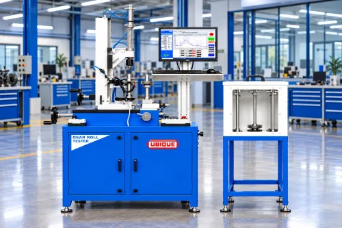
• Category: Automated Gear Metrology Systems
• Short Summary: Motorized vertical double-flank gear tester integrated with PC software for automated measuring and real-time analysis of Total Composite Error (TCE), Tooth-to-Tooth Error (TTE), Runout, Over ball diameter and Jerky rolling on shaft-integrated and long-profile gears.
Key Highlights
• Shaft-Optimal Vertical Alignment: Between-centers mounting eliminates sagging and bending during motorized inspection of pinion shafts.
• Automated Pass/Fail Verdicts: Software checks measured curves against defined tolerance limits for rapid production quality control.
• Real-Time Graphical Diagnostics: Live profile display of composite error waves, eccentricity, and tooth mesh defects directly on screen.
• Material: Machine bed manufactured from Seasoned and Stress relieved Casting and manually scraped to achieve required accuracy.
• Fast Quality Control: Quick results ideal for Quality labs.
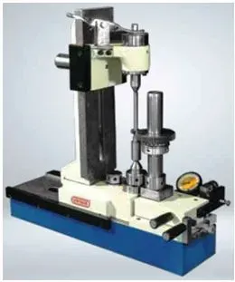
• Category: Quality Control & Gear Metrology Equipment
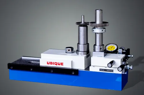
• Short Summary: Precision vertical double-flank gear tester engineered to measure total composite error specifically for shaft gears.
Key Highlights
• Shaft-Optimal Alignment: Vertical mounting between centers prevents sag and bending during inspection.
• Ergonomic Loading: Open column design simplifies clamping for longer shaft.
• Micron Repeatability: Linear optical scale delivers high-precision composite error detection.
• Material: Machine bed manufactured from Seasoned and Stress relieved Casting and manually scraped to achieve required accuracy.
• Fast Quality Control: Rapid manual loading ideal for production-line inspection.
• Versatile Mounting: Accommodates both shaft-type and bore-type precision gears.
Product Overview
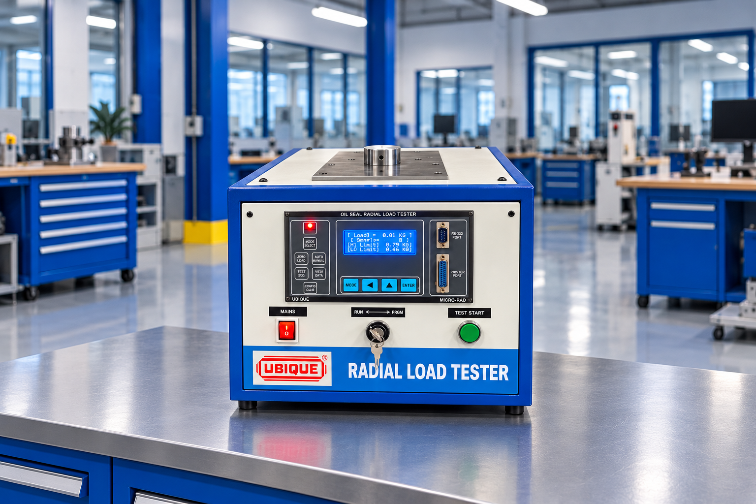
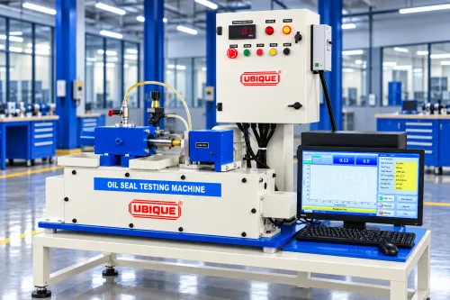
The UBIQUE Oil Seal Lip Radial Load Tester (Model OSRL) is designed to measure the force exerted by oil seal lip/s on the mating shaft in static condition. The machine is based on the test procedure laid down in SAE J1901 Split Shaft Method.
Test Method
The tester is based on the SAE J1901 Split Shaft Method for measuring the force exerted by oil seal lip/s on the mating shaft while the seal is in a static condition.
Dedicated Mandrels and Shaft Simulation
The machine is designed to simulate shaft diameters from 15 mm to 200 mm by using suitable size-specific dedicated mandrels. Dedicated tooling can therefore be selected according to the oil seal application and shaft diameter being evaluated.
Force Measurement and Digital Display
The tester incorporates a dedicated microcontroller and digital display. The force measuring unit can be selected in Newton (N), Kilogram-force (kgf) or Newton-Pi (NΠ), as specified for the machine.
Test Data Acquisition
The machine is supplied with dedicated Windows-based PC software for online uploading of test results. Test data can be uploaded as an .xls file with a date-time stamp using Microsoft Excel.
Typical Applications
• Oil seal manufacturing and quality control
• Automotive component manufacturing
• Oil seal inspection and testing
• Testing and quality-control laboratories
• Product development and evaluation of oil seal applications
Selected Users
The supplied UBIQUE product information lists users including Super Seals India Ltd., Paul Auto Components, LML Ltd., Swastik Rubber Products Ltd., Sundaram Industries Ltd., BMF Beltings Pvt. Ltd., Fenner India Ltd., Kay Kay Fluid Seals Ltd., Polybond India Pvt. Ltd., Suja Rubber Products Pvt. Ltd., Kross International, Endurance Technologies Ltd., Bruss North America, ESP Engineered Components Pvt. Ltd., Perfect Polymer and Fersa Bearings Spain.
Product Overview
UBIQUE Oil Seal Lip Opening Pressure Tester is designed for measuring the Lip Opening Pressure (LOP) of oil seals based on the test procedure outlined in SAE J946. The tester uses an electronic Mass Flow Controller to control and measure air flow at 10,000 cc/min and an electronic pressure sensor to sense the pressure registered during the test. A digital display provides the LOP reading.
Customised Mandrel Assembly
The mandrel assembly is custom-built to suit the individual oil seal. The supplied specification lists dedicated tooling ranges for oil seals with outside diameters up to 100 mm, 101–150 mm and 151–200 mm. The machine specification states a maximum oil seal OD of 300 mm.
Typical Applications
• Oil seal manufacturing and quality control
• Automotive component manufacturing
• Inspection and testing laboratories
• Product development and validation
• Testing of individual oil seal designs and sizes
Oil Seal Lip Opening Pressure Tester Manufacturer in [City]
UBIQUE Industrial Systems manufactures Oil Seal Lip Opening Pressure Testers for customers requiring SAE J946-based LOP testing. The system combines electronic flow control, pressure sensing, digital indication and dedicated tooling for individual oil seal applications. Replace [City] with the target city when this document is used as content for a city-specific website.
Product Overview
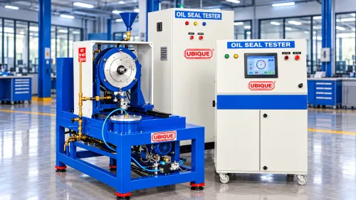
UBIQUE Oil Seal Endurance Tester is designed to evaluate the performance, endurance and durability of rotary shaft type oil seals under controlled operating conditions. Based on the test procedure outlined in SAE J10, the machine simulates important service conditions such as shaft rotation, elevated temperature, pressure, oscillation, dust and mud exposure.
The tester is built with a heavy-duty fabricated structure for reliable long-term operation. It uses dedicated tooling comprising a housing flange and shaft stub designed for the specific oil seal under test. The machine enables manufacturers, automotive component suppliers and testing laboratories to assess seal performance and measure oil leakage during endurance testing.
Controlled Endurance Testing
The machine allows the operator to create a test cycle by entering the oil seal identification, part number, housing and shaft dimensions, media temperature, shaft speed, direction of rotation, pressure settings, oscillation status, dust or mud chamber operation, test duration and number of cycles.
During the test, the HMI displays the programmed and actual test parameters. This enables the operator to monitor the test condition and record relevant observations. An online industrial PC with dedicated LabVIEW-based software is available as an accessory for multiple test programs and automatic data acquisition with date and time stamps.
Environmental Simulation
The Oil Seal Endurance Tester can simulate demanding operating environments. The heated media sump supports testing at temperatures up to 150°C. Regulated air pressure can be applied to reproduce pressure conditions. The optional dust chamber introduces agitated dust into the test area, while the optional mud chamber uses a motor-driven paddle stirrer to prevent settling of the test slurry.
Only one environmental chamber, either the dust chamber or the mud chamber, can be mounted on the housing flange away from the machine spindle at a time.
Typical Applications
• Oil seal performance, endurance and durability testing
• Automotive component manufacturing
• Oil seal manufacturing and quality control
• Research and development laboratories
• Product validation and design comparison
• Testing under heat, pressure, dust, mud and oscillation conditions
• Evaluation of oil leakage over a defined test cycle
Oil Seal Endurance Tester Manufacturer in [City]
UBIQUE Industrial Systems manufactures Oil Seal Endurance Testers for controlled performance and durability evaluation of rotary shaft type oil seals. The system combines dedicated application-specific tooling, variable shaft speed, heated test media, pressure and oscillation simulation, optional dust or mud exposure, HMI-based test control and oil leakage measurement.
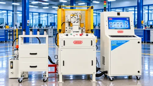
A half bearing shell testing machine verifies the fit, seating, geometry and load response of engine bearing shells before assembly. Ubique Systems can design application-specific nests, force and displacement measurement, variant identification and traceable acceptance logic around the customer’s bearing shell, housing and journal requirements.
What is the purpose of this machine?
Half bearing shells are precision engine components that support a rotating journal and help establish the required lubrication clearance. A dedicated test machine checks whether the correct shell variant is present and whether it meets the defined geometry, fit and seating requirements for the application.
The exact test method depends on the customer’s component design and quality plan. A machine may combine dimensional measurement, controlled loading, seating or crush-response measurement, presence verification, visual inspection and traceability. The final machine should be specified from the bearing drawing, material, coating, housing, journal, datum scheme and acceptance limits.
Why is half bearing shell EOL testing important?
Bearing-shell condition affects alignment, oil-film formation, friction, heat generation and engine durability. Wrong shell selection, incorrect wall thickness, poor seating, excessive clearance, insufficient crush or surface damage may not be obvious after a quick visual inspection. An EOL test can identify these conditions before the shell enters the engine assembly.
Typical working sequence
The shell is loaded into an application-specific nest and identified by part number, barcode or vision. The fixture establishes the required datum and mating condition. Sensors may measure wall thickness, position, seating, crush, force, displacement or clearance-related response. If a functional load test is required, the machine applies a controlled force and records the response. The software compares the values with the exact variant recipe and stores the result.
Typical machine features
• Customer-specific nest based on shell profile, housing and journal geometry.
• Poka-yoke for upper/lower, size, grade and variant identification.
• Force and displacement sensors for controlled load response.
• Dimensional, presence and vision inspection options.
• Automated recipe selection and barcode or Data Matrix traceability.
• Digital pass/fail report with configured limits.
• Optional modules for bearing seal, split bush or related components.
• Guarding and interlocks for safe production operation.
Similar or related machines to include
Related terms include engine bearing shell tester, connecting-rod bearing shell test machine, main bearing shell inspection machine, bearing crush test rig, bearing clearance test bench, split bush test rig, bearing seal tester and automotive bearing EOL inspection system.
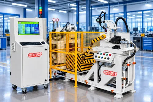
Ubique Systems’ control valve test rigs reproduce the hydraulic flow, pressure and loading conditions required to validate control valves used in tractor hydraulic lifts and other hydraulic applications. The machine measures pressure, flow, lift response, arm movement, relief behaviour and timing using configurable fixtures, instrumentation and PLC-based control.
What is the purpose of this machine?
A control valve regulates hydraulic oil flow and pressure to operate an actuator, lift or other hydraulic function. A control valve testing machine connects the valve to a controlled hydraulic circuit and applies the operating conditions required by the application. It can vary input flow, generate hydraulic or dead-weight loading, measure pressure and flow, and measure the resulting motion of the connected mechanism.
Ubique’s existing control valve test rig is positioned around the hydraulic lift control valve used on tractor transmissions, while also being described as customizable for other hydraulic applications.[7]
Why is control valve EOL testing important?
A valve can be dimensionally correct and still deliver the wrong pressure, unstable flow, slow response, excessive drop or incorrect relief behaviour. Because the valve controls a hydraulic function, a defect may affect lift performance, load holding, operator control or system protection. EOL testing validates the entire functional response of the valve under controlled load instead of relying only on visual or dimensional inspection.
Typical working sequence
The correct valve variant is identified by barcode or production program. The valve is secured in the fixture and connected through quick-release hydraulic couplings. The machine starts the filtered oil circuit and sets the required input flow. Hydraulic or dead-weight loading is applied. The control system measures no-load and loaded pressures, flow, arm displacement, lift time, angle, travel and relief-valve behaviour. The result is evaluated against variant-specific limits and stored for traceability.
Typical machine features
Ubique’s first-party page describes variable flow through a speed-controlled motor, variable loads commonly configured through a hydraulic circuit and cylinders, optional hydraulic or dead-weight loading, quick-release couplings, pressure transducers, high-back-pressure flowmeters, closed-loop oil supply and filtration, wire-encoder length measurement, arm-drop measurement, PC plus PLC control, LabVIEW/SCADA/.NET software, MES transfer, barcode, printing and automatic recipe selection.[7]
Recommended feature wording:
• Application-specific hydraulic circuit and valve fixture.
• Variable flow and configurable hydraulic or dead-weight loading.
• Accurate pressure and flow measurement.
• Position, angle, lift time and drop measurement.
• Filtered closed-loop oil supply.
• Quick-release hydraulic connections and safe interlocks.
• Multi-variant recipe control with barcode identification.
• PLC/PC software, reports and MES connectivity options.
Similar or related machines to include
Related search terms include hydraulic control valve test rig, tractor control valve testing machine, hydraulic lift test rig, spool valve testing machine, hydraulic pressure-flow test bench, relief valve pressure tester, hydraulic valve response tester and valve functional EOL tester.
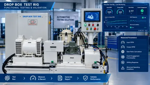
A drop box test rig validates the tractor transfer assembly that engages and disengages front-wheel or four-wheel drive. Ubique Systems’ customized machine controls input speed, loading, gear engagement and oil condition while measuring output response, speed relationship, ratio and load behaviour before the drop box is installed in the transmission.
What is the purpose of this machine?
A drop box, also called a transfer box in some applications, transfers drive from the transmission to a front axle or another output path. The drop box test machine validates the completed assembly as a standalone unit before it is mounted on the tractor transmission.
The machine uses splined or application-specific adapters to connect the drive and output shafts. It can rotate the unit at variable speed, apply controlled load, command or support gear selection, and monitor oil filling, draining, filtration and interlock conditions.
Why is drop box EOL testing important?
Incorrect speed ratio, incomplete engagement, abnormal load response, poor lubrication, shaft misalignment or assembly errors can compromise 2WD/4WD operation and drivability. Testing the drop box before transmission integration helps prevent downstream rework and gives the manufacturer a clear record of functional acceptance.
Typical working sequence
The drop box is loaded into a poka-yoke fixture and identified. The machine checks seating and adapter engagement, confirms oil level and safety interlocks, fills or conditions oil if required, then drives the input at the programmed speed. The operator or automatic mechanism selects the required position. The loading unit applies the defined load and the machine measures input and output speeds, ratio and load response. At the end, oil may be drained, the result recorded and a barcode or report printed.
Typical machine features
Ubique’s first-party drop-box material describes variable input speed, loaded testing, settable loading, programmable test parameters, automatic oil filling and draining, manual shifting with automatic shifting available on request, closed-loop filtration, oil-level interlocks, poka-yoke, splined adapters, flexible couplings, PC/PLC control, barcode and multiple variant programs.[6]
Similar or related machines to include
Related terms include tractor transfer case test rig, 4WD engagement testing machine, transfer box testing machine, front-wheel drive engagement tester, tractor drop box EOL tester, transfer case ratio test bench and loaded transfer assembly test rig.
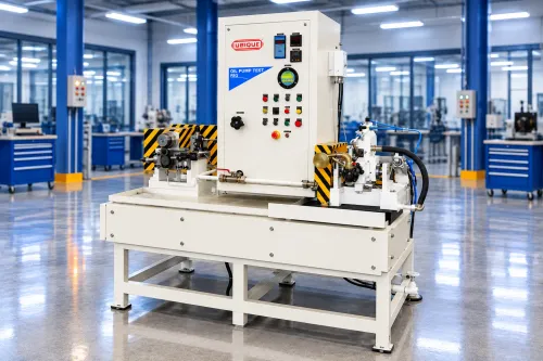
Ubique Systems designs oil pump and water pump test rigs that reproduce application-specific speed, back pressure, temperature and suction conditions. The system measures pump flow and pressure response at defined operating points, helping manufacturers verify fluid-delivery performance before the pump assembly reaches the vehicle.
What is the purpose of this machine?
A pump test machine validates whether an oil pump or water pump delivers the required fluid flow under the conditions expected in the application. The machine drives the pump at controlled speeds and circulates oil, coolant or another specified test fluid through a controlled circuit. It can generate defined back pressure, condition the fluid temperature, simulate negative suction head and measure the pump’s response.
The oil pump version is suited to engine lubrication, transmission lubrication, hydraulic and other fluid-delivery applications. The water pump version is suited to engine cooling, thermal management and coolant circulation. The test rig can be designed for multiple pump variants with limited fixture changeover.
Why is pump EOL testing important?
A pump may rotate correctly and still fail to deliver sufficient flow at operating pressure or temperature. Low flow, excessive flow, pressure instability, internal slip, inlet restriction, cavitation risk or wrong rotation can lead to lubrication failure, overheating or insufficient cooling. EOL pump testing measures the actual performance curve of the finished assembly and provides an objective release decision.
Typical working sequence
The pump is located in a dedicated fixture and identified by barcode. The correct recipe sets speed, temperature, pressure, suction and test duration. The drive motor rotates the pump while the circuit controls back pressure and fluid condition. Flow, pressure, temperature and input conditions are continuously measured. The software compares the values with the programmed acceptance window, stores the result and can transfer data to MES.
Typical machine features
Ubique’s first-party oil-pump and water-pump pages describe customer-specific fixtures, variable speed through an AC variable drive controlled motor, variable back pressure through a manual or servo-controlled valve, high-back-pressure flow measurement, multiple circuit lines, controlled fluid temperature, suction-head simulation, PC plus PLC software, MES transfer, barcode, variant programs and closed-loop filtration.[4][5]
Recommended feature wording:
• Oil or coolant circuit designed for the application.
• Controlled speed, back pressure and test-fluid temperature.
• Manual or servo-controlled pressure regulation.
• Flow measurement at zero and defined back pressure.
• Negative suction-head simulation where required.
• Multiple circuits for multi-variant or multi-pump testing.
• Closed-loop filtration and fluid conditioning.
• Automated fill, drain and level interlocks where required.
• PC/PLC control, barcode recipes, reports and MES connectivity.
Similar or related machines to include
For oil pumps: engine oil pump test rig, transmission oil pump tester, lubrication pump test bench, hydraulic pump flow test machine, automotive pump performance tester, oil pump pressure-flow test rig.
For water pumps: automotive water pump tester, engine coolant pump test rig, vehicle cooling system pump tester, electric water pump test bench, coolant flow test machine, thermal-management pump EOL tester.
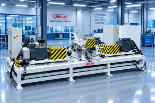
Ubique Systems manufactures customized front axle and rear axle test rigs for automotive, tractor, commercial vehicle, defence and e-mobility applications. The machine can validate speed, torque transmission, ratio, rotation, drag, backlash, temperature, leakage and NVH according to the customer’s axle design and acceptance criteria.
What is the purpose of this machine?
An axle testing machine checks a complete front axle, rear axle, drive axle or axle subassembly before shipment or vehicle integration. The test rig supports the assembly at its functional datums, connects the drive and output interfaces, and applies controlled speed and loading. Depending on the axle architecture, the system can test differential operation, wheel-end response, gear mesh, lubrication and noise behaviour.
Ubique’s existing product structure distinguishes front axle and rear axle test rigs, allowing the website to create separate application pages while keeping them within one axle testing family.[3]
Why is axle EOL testing important?
The axle is a critical driveline and chassis assembly. Incorrect gear mesh, wrong ratio, bearing drag, excessive backlash, poor lubrication, seal leakage or assembly misalignment can result in noise, heat generation, poor drivability or premature wear. Detecting these conditions after vehicle assembly can cause line stoppage and expensive rework. EOL axle testing provides a controlled release gate before the unit reaches the vehicle.
Typical working sequence
The axle is loaded using a customer-specific fixture and identified by barcode. The machine connects to the input pinion, axle shafts, hubs or output interfaces as required. The control system commands the defined speed and load profile. It may run forward and reverse directions, check ratio, measure torque and capture vibration or acoustic signals. The software records the result against the axle serial number and can interface with MES or print a report.
Typical machine features
• Front axle and rear axle configurations.
• Custom supporting structure and shaft or hub adapters.
• Variable-speed drive and optional controlled loading.
• Torque transducer and high-resolution speed sensing.
• Forward/reverse testing and direction verification where required.
• NVH acquisition option for gear, bearing and driveline noise.
• Guarding, interlocks, poka-yoke and automatic result handling.
• Barcode, printer, PC/PLC control and MES connectivity options.
Similar or related machines to include
Related search and product terms include front axle test rig, rear axle test rig, drive axle test machine, differential test bench, final drive test rig, e-axle testing machine, axle torque test bench, axle gear ratio tester, axle NVH test rig, tractor axle test machine and automotive driveline EOL tester.
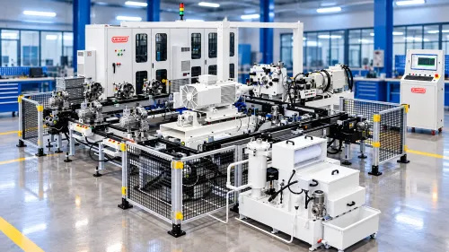
Ubique Industrial Systems’ gearbox and transmission testing machines are customized End-of-Line test rigs for tractor, passenger vehicle, commercial vehicle, heavy vehicle and e-mobility transmissions. The system can verify ratios, speed, torque transfer, gear engagement, shift behaviour, hydraulic functions, oil flow and NVH under defined operating conditions, with variant-specific recipes and traceable results.
What is the purpose of this machine?
A transmission testing machine checks whether a completed gearbox or transmission assembly performs its intended mechanical and hydraulic functions before it is installed in a vehicle or released to the next stage. The machine couples the transmission to a controlled drive system and, where required, a controlled loading system. The test sequence can command different gears, speeds, directions and load conditions while sensors record the response.
The machine may be configured for a tractor transmission, manual transmission, automatic transmission, reduction gearbox, e-axle gearbox, transfer assembly or another customer-defined powertrain unit. The fixture, splined adapters, couplings, oil circuits, electrical interfaces and software are designed around the unit-under-test and its variant family.
Typical working sequence
The operator or automated material-handling system identifies the transmission by barcode or production ID. A poka-yoke fixture confirms correct variant orientation and seating. The machine connects the required shafts, hydraulic lines, lubrication circuit and electrical interfaces. The system may fill or condition oil before testing, select a customer-defined recipe, rotate the input at programmed speeds, engage selected gears, apply a defined load and record the resulting measurements. At the end of the sequence, the system generates a pass/fail result, stores the data and can print or transmit the report to the customer’s MES.
Typical machine features
Ubique’s first-party transmission material describes customized fixtures for multiple transmission variants, optional loaded testing, variable load and speed, automatic adaptation, automatic motor engagement, torque transducers, high-resolution incremental encoders, PC and PLC control, dedicated software, MES linkage, barcode scanning and printing, and turnkey functions such as oil filling and draining.
Category: Quality Control & Gear Metrology Equipment
Short Summary: High-precision horizontal double-flank gear tester designed to measure total composite error in micro to small gears
Key Highlights
Micron-Level Precision: Low-friction linear bearings ensure high repeatability.
Material: Machine bed manufactured from Seasoned and Stress relieved Casting and manually scraped to achieve required accuracy.
Fast Quality Control: Rapid manual loading ideal for production-line inspection.
.